Connecting a low cost TDR moisture content/EC/temp sensor to a NodeMCUv3
I have discussed moisture content sensors extensively in the past. I have written posts about the use of capacitive moisture sensors to measure volumetric moisture content, including how to create sensor stations and how to calibrate them. However, while capacitive moisture content sensors can be a low cost alternative for low resolution monitoring of moisture content, more precise applications require the use of higher accuracy sensors, such as Time Domain Reflectometry (TDR) sensors. In this post I am going to show you how to connect a low cost microcontroller (NodeMCUv3) to a low cost TDR moisture content sensor. Note, some of the product links below are amazon affiliate links, which help support this blog at no additional cost to you.

While popular sensors like Teros-12 sensors cost hundreds of dollars, lower cost alternatives have been created by Chinese manufacturers. Using this github repository by git user Kromadg, I have been able to interface some of these low cost TDR sensors with a NodeMCUv3. The NodeMCUv3 is a very low cost microcontroller unit that you can get for less than 5 USD a piece. It is also WiFi enabled, so this project can be expanded to send data through Wifi to use in datalogging or control applications. For this project you will need the following things:
- Micro USB cable
- NodeMCUv3
- THC-S RS485 sensor (Make sure to get the THC-S model)
- TTL to RS485 communication board
- Breadboard and jumper cables to make connections or cables and a soldering kit to make final connections.
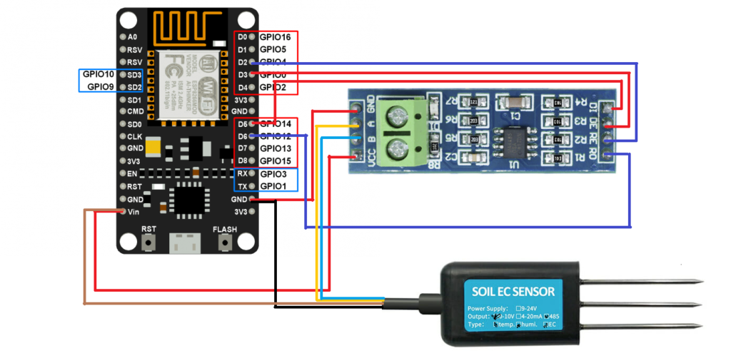
The above diagram shows you how to connect the sensor, TTL-to-RS485 communication board and the NodeMCUv3. You will also want to make sure you install the ESP Software serial library in your Arduino IDE, as the normal Software Serial library won’t work. You can do this by downloading the zipped library from github and then using the Sketch->Include Library menu option. Once you do so, you can upload the following code into your NodeMCUv3.
#include <SoftwareSerial.h>
#include <Wire.h>

// This code is a modification of the code found here (https://github.com/kromadg/soil-sensor)

#define RE D2
#define DE D3

const byte hum_temp_ec[8] = {0x01, 0x03, 0x00, 0x00, 0x00, 0x03, 0x05, 0xCB};
byte sensorResponse[12] = {0x00, 0x00, 0x00, 0x00, 0x00, 0x00, 0x00, 0x00, 0x00, 0x00, 0x00, 0x00};
byte sensor_values[11];

SoftwareSerial mod(D6, D5); // RX, TX

void setup() {
    Serial.begin(115200);
    pinMode(RE, OUTPUT);
    pinMode(DE, OUTPUT);
    digitalWrite(RE, LOW);
    digitalWrite(DE, LOW);
    delay(1000);
    mod.begin(4800);
    delay(100);
}

void loop() {
    /************** Soil EC Reading *******************/
    digitalWrite(DE, HIGH);
    digitalWrite(RE, HIGH);
    memset(sensor_values, 0, sizeof(sensor_values));
    delay(100);

    if (mod.write(hum_temp_ec, sizeof(hum_temp_ec)) == 8) {
        digitalWrite(DE, LOW);
        digitalWrite(RE, LOW);
        for (byte i = 0; i < 12; i++) {
            sensorResponse[i] = mod.read();
            yield();
        }
    }

    delay(250);

    // get sensor response data
    float soil_hum = 0.1 * int(sensorResponse[3] << 8 | sensorResponse[4]);
    float soil_temp = 0.1 * int(sensorResponse[5] << 8 | sensorResponse[6]);
    int soil_ec = int(sensorResponse[7] << 8 | sensorResponse[8]);

    /************* Calculations and sensor corrections *************/

    float as_read_ec = soil_ec;

    // This equation was obtained from calibration using distilled water and a 1.1178mS/cm solution.
    soil_ec = 1.93*soil_ec - 270.8;
    soil_ec = soil_ec/(1.0+0.019*(soil_temp-25));

    // soil_temp was left the same because the Teros and chinese sensor values are similar

    // quadratic aproximation
    // the teros bulk_permittivity was calculated from the teros temperature, teros bulk ec and teros pwec by Hilhorst 2000 model
    float soil_apparent_dieletric_constant = 1.3088 + 0.1439 * soil_hum + 0.0076 * soil_hum * soil_hum;

    float soil_bulk_permittivity = soil_apparent_dieletric_constant;  /// Hammed 2015 (apparent_dieletric_constant is the real part of permittivity)
    float soil_pore_permittivity = 80.3 - 0.37 * (soil_temp - 20); /// same as water 80.3 and corrected for temperature

    // converting bulk EC to pore water EC
    float soil_pw_ec;
    if (soil_bulk_permittivity > 4.1)
        soil_pw_ec = ((soil_pore_permittivity * soil_ec) / (soil_bulk_permittivity - 4.1) / 1000); /// from Hilhorst 2000.
    else
        soil_pw_ec = 0;

    Serial.print("Humidity:");
    Serial.print(soil_hum);
    Serial.print(",");
    Serial.print("Temperature:");
    Serial.print(soil_temp);
    Serial.print(",");
    Serial.print("EC:");
    Serial.print(soil_ec);
    Serial.print(",");
    Serial.print("READEC:");
    Serial.print(as_read_ec);
    Serial.print(",");
    Serial.print("pwEC:");
    Serial.print(soil_pw_ec);
    Serial.print(",");
    Serial.print("soil_bulk_permittivity:");
    Serial.println(soil_bulk_permittivity);
    delay(5000);
}
Note that RE and DE are not placed on digital pins 2 and 3, as other pins in the NodeMCUv3 carry out other functions and the board will not initialize if it has the RS485-to-TTL communicator connected through those pins. The R0 and RI pins are connected to digital pins D5 and D6, this is because in the NodeMCUv3 pins D7 and D8 are used in serial communication by the Serial swap command and therefore create conflicts if you use them with SoftwareSerial. The above digital pin distribution is one of the few that works well. Note that connecting RE or DE to digital pin 4 also works, but this means the blue LED on the NodeMCUv3 is powered on every time there is serial communication, a potentially undesirable effect if you’re interested in battery powering the device.
The board should now be printing all the measurements on your serial connection, so you should be able to see the readings through the Serial Monitor in the Arduino IDE. In the future I will be sharing how to expand this code to include WiFi and MQTT communication with a MyCodo server.
If you use this code please share your experience in the comments below!