Creating a pH/EC wireless sensing station for MyCodo using an Arduino MKR Wifi 1010
There are multiple open-source projects available online for the creation of pH/EC sensing stations for hydroponics. However, all of the ones I have found use a single Arduino or Raspberry Pi to perform the measurements and store any data, making them unsuitable for applications where more flexibility is needed. For example, a facility using multiple different reservoir tanks for nutrient storage might require multiple pH/EC sensing stations, and single-board wired setups would be unable to accommodate this without a lot of additional development. In this post, I am going to show you a simple pH/EC sensing station I built with an Arduino MKR Wifi 1010 that can communicate with a MyCodo server using the MQTT protocol. Multiple sensing stations could be built and all of them can communicate with the same MyCodo server.
This project makes use of the small pH/EC boards provided by uFire, which have a lower cost compared to those provided by companies like Atlas, but do have adequate electrical isolation to avoid problems in readings when multiple electrodes are put in the same solution. This is a substantial improvement over other low-cost boards where using multiple probes can cause heavy electrical noise and interference. In order to build this project you will require the following materials:
Note, some of the links below are amazon affiliate links. This means that I get a small commission if you purchase through these links at absolutely no extra cost to you. The links to other websites are not affiliate links.
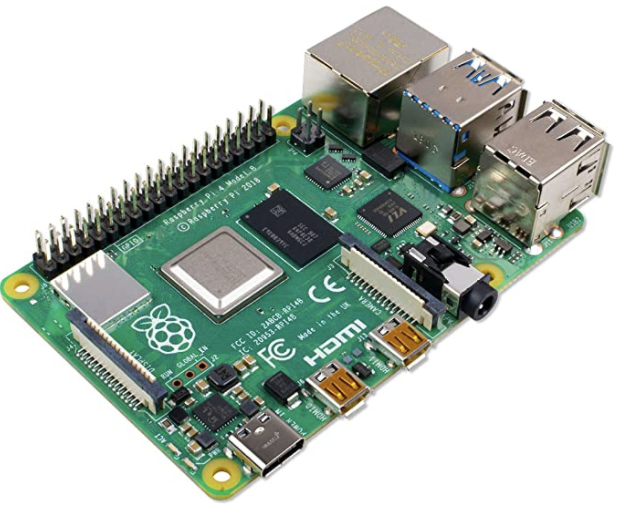
- Arduino MKR Wifi 1010
- uFire pH probe
- uFire EC probe
- A rugged pH probe with a VNC connector
- An rugged EC probe with a VNC connector
- Two Qwiic-to-Qwiic connectors
- One Qwiic-to-male connector
- A project box to put everything inside (optional)
- A micro USB cable
The code for the project is shown below:
#include <uFire_EC.h>
#include <uFire_pH.h>
#include <WiFiNINA.h>
#include <ArduinoMqttClient.h>
#define SECRET_SSID "ENTER WIFI SSID HERE"
#define SECRET_PASS "ENTER WIFI PASSWORD HERE"
//calibration solutions used
#define PH_HIGH_SOLUTION_PH 7.0
#define PH_LOW_SOLUTION_PH 4.0
#define EC_HIGH_SOLUTION_EC 10.0
#define EC_LOW_SOLUTION_EC 1.0
#define CALIBRATION_TEMP 20.0
// topics for the mqtt sensors
// Make sure all stations have different topics
#define EC_TOPIC "EC1"
#define PH_TOPIC "PH1"
#define CALIB_TOPIC "CALIB1"
#define MQTT_BROKER "ENTER MQTT SERVER IP HERE"
#define MQTT_PORT 1883
int status = WL_IDLE_STATUS; // the Wifi radio's status
String message;
uFire_pH ph;
uFire_EC ec;
WiFiClient wifiClient;
MqttClient mqttClient(wifiClient);
void check_connection()
{
if (!mqttClient.connected()) {
WiFi.end();
status = WiFi.begin(SECRET_SSID, SECRET_PASS);
delay(10000);
if (!mqttClient.connect(MQTT_BROKER, MQTT_PORT)) {
Serial.print("MQTT connection failed! Error code = ");
Serial.println(mqttClient.connectError());
delay(100);
}
mqttClient.subscribe(CALIB_TOPIC);
}
}
void setup()
{
Serial.begin(9600);
while (!Serial);
// connect to wifi and mqtt broker
check_connection();
// coorectly initialize the uFire sensors
// note the Wire.begin() statement is critical
Wire.begin();
ec.begin();
ph.begin();
}
void loop()
{
// mqtt keep alive
mqttClient.poll();
// read messages
message = "";
while (mqttClient.available()) {
message += (char)mqttClient.read();
}
// execute calibration if requested
Serial.println(message);
if (message == "EC1_HIGH") ec.calibrateProbeHigh(EC_HIGH_SOLUTION_EC, CALIBRATION_TEMP);
if (message == "EC1_LOW") ec.calibrateProbeLow(EC_LOW_SOLUTION_EC, CALIBRATION_TEMP);
if (message == "PH1_HIGH") ph.calibrateProbeHigh(PH_HIGH_SOLUTION_PH);
if (message == "PH1_LOW") ph.calibrateProbeLow(PH_LOW_SOLUTION_PH);
// Measure EC
ec.measureEC();
Serial.println((String) "mS/cm: " + ec.mS);
// Measure pH
ph.measurepH();
Serial.println((String) "pH: " + ph.pH);
// Ensure the wifi and mqtt connections are alive
check_connection();
// post EC to MQTT server
mqttClient.beginMessage(EC_TOPIC);
mqttClient.print(ec.mS);
mqttClient.endMessage();
// post pH to MQTT server
mqttClient.beginMessage(PH_TOPIC);
mqttClient.print(ph.pH);
mqttClient.endMessage();
// ensure sensors are not probed too frequently
delay(1000);
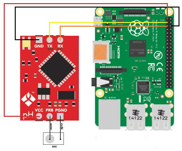
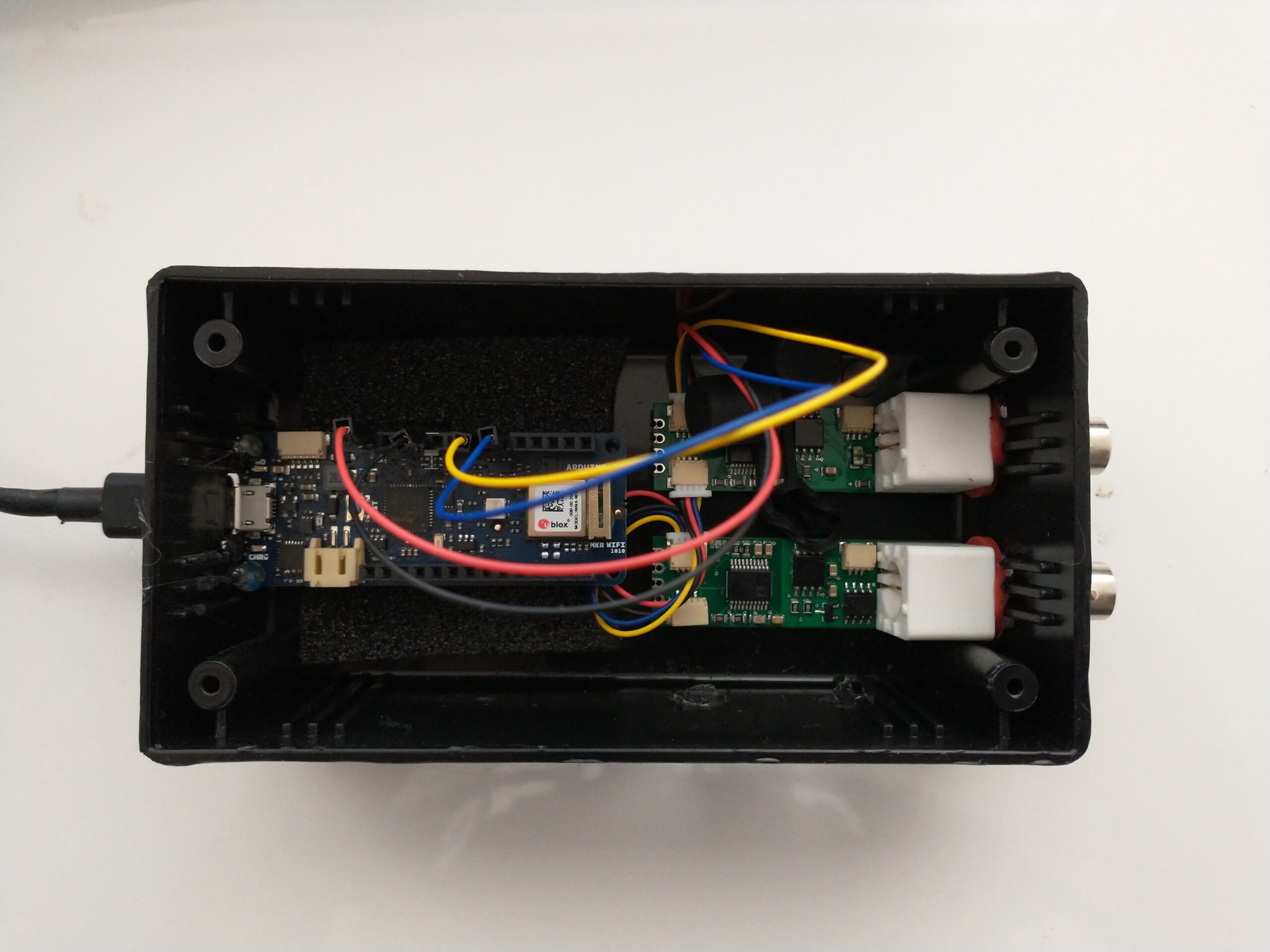
}Once you get all the materials you should first assemble the components. Connect the pH and EC board together using the Qwiic-to-Qwiic connector, then use the Qwiic-to-male connector to hook up one of these boards to the Arduino (doesn’t matter which one). Connect the black cable to ground, red cable to 5V, blue cable to SDA, and yellow cable to SCL. Set up your board according to the instructions in the Arduino MKR wifi 1010 getting started page, modify the code above to properly include information about your wifi network, calibration solutions, and MQTT server, then upload the code. The Arduino will connect to your Wifi and MQTT servers and automatically reconnect when there are connection issues.
The above code will also post the readings of the pH and EC sensors to topics PH1 and EC1 respectively if you add an input in MyCodo to capture these readings you should be able to store them and take control actions using the MyCodo interface. Additionally, the Arduino code will respond to calibration requests published to the topic “CALIB1”. For example, if you want to calibrate your EC sensor with a two-point calibration method with a standard solution with an EC of 10mS/cm, you would put the electrode in the calibration solution, then send the message “EC1_HIGH” to the CALIB1 topic and the Arduino will perform the task as requested. The code assumes you will want to do 2 point calibrations for both EC and pH, with the calibration events triggered by EC1_HIGH, EC1_LOW, PH1_HIGH, and PH1_LOW. Note that the definition of the EC and pH values of the calibration solutions should be changed to the solutions you will be using within the code. The high/low values in the code, as is, are 10mS/cm|1mS/cm for EC and 7|4 for pH.