Making the most out of your hydroponic setup’s logged sensor and control data

If you have a hydroponic crop with a data logging and automated control solution, you probably have a lot of sensor and control data recorded that could be useful to take your crop’s results to the next level. In this post, I am going to talk about some things that you could be doing with these stored data. You will see how the usage of this data opens up many possibilities and that even implementing the most basic of these suggestions could lead to important improvements in your understanding of your crop and its results.

Use of different moving average to smooth out sensor readings.

The lowest hanging fruit to take advantage of logged data is to be able to download the data and put it into a database structure that you can properly query and search. Most data logging solutions record the data in either very simple structures, like csv files, or non-relational databases – like MongoDB – which are rather limited and do not allow for the degree of versatility that a true relational database engine offers. Having the data in a properly built database will allow you to start using it in a creative way. For example, with the data in a proper database, it becomes possible to create a custom data visualization that can help you understand what’s going on inside your growing environment.

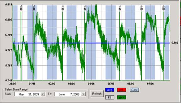
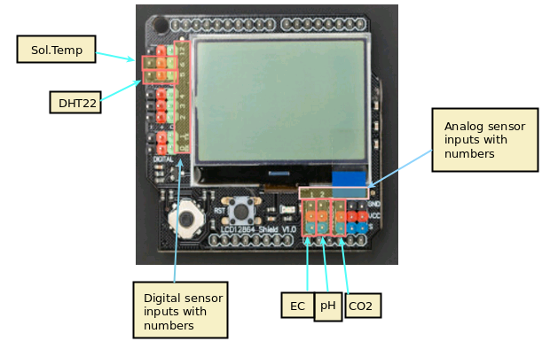
The images in this post show you some examples of this. The first one shows a simple example where a rather noisy humidity sensor is smoothed out using different moving averages, these averages can then be used to implement more effective control algorithms. The second image shows a detailed map of the temperature and humidity values experienced in a room, colored by the hour of the day. We can use this plot to easily locate where problematic times and VPD conditions might be, just by looking at when extreme readings happen. This behavior would be harder to observe and diagnose on a regular VPD Vs Time plot. Regular data logging web interfaces and platforms will not allow you to create plots of this sort, which is why putting your data into a proper DB and manipulating it to create custom visualizations can be very powerful.

Relative Humidity Vs Temperature map colored as a function of the hour of the day for a growing room being constantly monitored

The most powerful uses of the data come into play when you actually piece together your control and sensor data. Say you have an AC system coupled with a temperature sensor but you have a lot of other temperature and humidity readings and you also know the age of your plants at each point in time. Using this, you can create an advanced control algorithm where a system will use all of this additional information to know when to trigger AC systems and dehumidifiers to control the environment. Having a lot of logged data from a set point control system is a great starting point to train a reinforcement learning algorithm for climate control, since we know which control actions were taken at each point in time and we know the effect these had. Implementing such control mechanisms can lead to control systems that avoid spikes in humidity and temperature across light on/off cycles, greatly smoothing out the environmental transitions for your crops.

Finally, there is also the potential to improve yields by gathering detailed mappings of yield data in a room and relating these yields with environmental sensors. If you have several different sensors in a room and you know the yield that you obtained on a per-plant basis, then you can create a map of all the yields in a room in order to see if there are important disparities in your yields because of differences in local humidity, temperature, light or air circulation levels. This can lead to important insights that can help better adjust climate conditions for the entire grow room. If multiple rooms are available, the information about environmental sensor data can be related to yields in order to stir all rooms towards more favorable conditions.

For example, after analyzing yield and temperature data from multiple growing cycles of one of my customers, we realized that the greenhouse with the lowest temperature standard deviations between sensors was giving the best yields, we then implemented better control algorithms on the other greenhouses to prevent this from happening, obtaining significantly better results across the board after that.

Data is a treasure. If you have been recording judicious sensor, climate control, and yield data through time, you’re probably sitting on a gold mine that you haven’t exploited yet. If you’re interested in using my help to do so, please consider booking an hour of consultation time with me so that we can discuss your needs and how we could leverage your data to improve your growing results.


The cricket IoT board: A great way to create simple low-power remote sensing stations for hydroponics

When you monitor variables in a hydroponic plant where more than a few plants exist, it becomes important to be able to deploy a wide array of sensors quickly and to be able to set them up without having to lay down a couple of miles of wire in your growing rooms or greenhouses. For this reason, I have been looking for practical solutions that could easily connect to Wi-Fi, be low powered, allow for analogue sensor inputs and be more user friendly than things like ESP8266 boards that are often hard to configure and sometimes require extensive modifications to achieve low power consumption. My quest has ended with the finding of the “cricket” an off-the-shelf Wi-Fi enabled chip that fulfills all these requirements (you can find the sensor here). Through this post, I will talk about why I believe it’s such a great solution to deploy sensors in a hydroponic environment. It is also worth mentioning that this post is not sponsored.

The cricket IoT board by ThingsOnEdge

When I seek to create custom monitoring solutions for hydroponic crops, one of the first requirements that comes to mind is the ability to connect through wifi effectively and be able to deliver the measurements to computers without needing wires. The cricket does this without any modifications, when you power it on it creates its own wifi hotspot that you can connect to, where you use a web interface to configure the device to connect to the normal network.

Besides connecting to the Wi-Fi, the next problem I often face is having the ability to have a proper protocol to communicate between devices. The MQTT standard has been my preferred solution – due to how easy it is to receive and relay information – so I always seek boards that are able to easily hook up to an MQTT server once they are in a Wi-Fi network. The cricket achieves this effortlessly as well, as MQTT is part of its basic configuration, which allows you to connect it with your MQTT server and relay its data right off the bat.

One of the simplest but most powerful applications for hydroponics is to hook up a capacitive moisture sensor to a cricket board and have this relay the data to an MQTT server. You can set this up to even send the data to an MQTT server powered by ThingsOnEdge, so that you don’t have to send the data to your own server. This setup can be battery powered with 2 AA batteries, it can then give you readings for several months, depending on how often you want the sensor to broadcast its readings. You can read more about how to carry out this project here.

A complete assembled device
cricket hooked to a capacitive sensor, image taken from here.

One of the disadvantages of the cricket – the main reason why it won’t fully replace other boards for me – is that it only has one analog sensor and one digital sensor input. This means that you’re limited to only two sensors per cricket and you also have an inability to use more advanced input protocols, such as the i2c protocol that is used by a wide variety of sensors. If you lack i2c it means you’re going to miss the opportunity to use a lot of advanced sensors, many of which I consider basic in a hydroponic setup, such as the BME280 sensors (see here why).

Although it is not a perfect sensor, the cricket does achieve two things that make it a great intro for people who want to get into IoT in hydroponics or those who want to setup a couple of low-power sensor stations with absolutely no hassle. The first is that it achieves simple configuration of both Wi-fi and MQTT and the second is that it simplifies the power consumption aspects, making it very easy to configure things such as sleep times, sensor reading intervals, and how often the sensor tries to relay those readings to the MQTT server. All-in-all, the cricket is a great starting point for those who want to get going with custom IoT in hydroponics with the least possible hassle.


Timing irrigations with moisture sensors in hydroponics

After discussing the different types of off-the-shelf sensors for measuring moisture in hydroponics (1,2,3), we are now going to explore the practical use of these sensors to time irrigations within a hydroponic crop. In this post, I’m going to share with you some of the key aspects of timing irrigations using moisture sensors as well as some useful resources I have found in the scientific literature that discuss this problem. We will mostly discuss sensor calibration, placement, and maintenance.

Image result for moisture sensor calibration curve
Some sample curves of volumetric water content as a function of sensor output. Taken from here.

In principle, the use of sensors to perform irrigations sounds simple. Wait till the sensor tells you there is little water in the media, turn on irrigation, wait till the sensors says there is enough water, turn irrigation off and wait for the process to repeat. However, there are several issues that complicate the problem, which need to properly considered if you want to successfully use these sensors for irrigation. The first such issue is the “set point” of the irrigation – when a sensor triggers an irrigation event – and how we can determine this.

Ideally, the first thing you will do with a sensor is calibrate it for your particular media to ensure that you can equate a given sensor reading with a given moisture content. The procedure below describes how this is can be done:

  1. Fill a container of known volume with drain holes with fully dry media without any plants.
  2. Weigh this full container.
  3. Insert the moisture sensor in it and take measurements till you have a stable reading. This will be the sensor set point.
  4. Wet the media with nutrient solution until there is substantial run-off coming off the bottom.
  5. Wait till the run-off stops.
  6. Weigh the media and take one moisture sensor reading every 1-2 hours, recording the time of each reading, until the media goes back to within 10% of the value of the initial reading.

With this data you can plot a graph of sensor signal vs water content (measured weight – dry weight) that you can use to determine what different signals from the sensor correspond in terms of amounts of water within the media. You can translate that water weight into volumetric water content by calculating the volume of water from the weight and then diving that by the total volume of the media. You should in the end arrive to curves like the ones shown above, where you can use regression analysis to create a relationship between moisture content and the sensor signal.

With the sensors now calibrated you can now decide on a set point for the irrigation based on how much dry back you desire. The optimal point for this will depend on your VPD and your growing objectives – whether you want to save water, maximize yields, etc – but starting with irrigations at a 50% dry-back point is usually a good idea, if no other guidelines exist. Some plants species are not very sensitive to this point – see this paper on basil – provided that you allow for enough dry-back for adequate oxygenation of the root system. By allowing deeper dry-backs you can save on water, although this can be problematic if your irrigations are done with nutrient solutions of significantly high strength. The ratio of plant size to media volume will also play a role as larger plants in smaller containers will tolerate shallower dry-backs as the total amount of water in the media will be smaller.

When an irrigation event is triggered it is also worth considering for how long this event will happen. If you water only till the sensor gives you a high moisture content reading, then there will be very little run-off and nutrients will tend to accumulate in the media and imbalances will be created since nutrients that are not absorbed cannot be leached out. For this reason, irrigations are usually continued for several minutes after sensors reach their high moisture reading, in order to ensure that enough run-off is collected to avoid these problems.

Sensor placement is also going to be critical for irrigation timing since you want to ensure that all plants are properly watered. Since irrigation events will generally be triggered by a single sensor, it is up to the grower to decide whether the risk of under or over watering is more acceptable. If the risk of underwatering is considered more important, the sensor will usually be placed in the plant that is largest, has the location with the micro-climate with the highest VPD, and which receives the most light. This is going to be the plant with the highest water demand and most likely the first to need irrigation, if you irrigate whenever this plant needs water, then almost everything else will be at a point of higher moisture content. This can be a dangerous game though, especially if over-watering can be problematic. In these cases, it is usually better to have multiple sensors and irrigation zones and make decisions based on more complex control processes. You can read more about irrigation timing and irrigation in hydroponics in general here.

The last important point here is sensor maintenance. Assuming that moisture sensors will always work in the same way can be a recipe for disaster because these sensors can deteriorate due to a variety of reasons. Since they are exposed to high-salinity, wet environments, contacts can corrode, leads can break and salts can accumulate within sensor structures. For this reason, it is good practice to wash these sensors with distilled water with some frequency – usually I recommend at least once per month – and to recalibrate the sensors at least once per year. It is also good to keep a a couple of already calibrated sensors in reserve, such that these sensors can be deployed quickly if an irrigation sensor fails. To be safer, have irrigations controlled by measurements taken by two sensors in the same plant and be alerted if the measurements of these sensors diverge, this usually indicates that a sensor has deteriorated and needs to be changed.


Hardware for building a wifi-connected DIY monitoring/control system for a hydroponic crop

Success in hydroponic systems can be increased by having adequate control over a wide array of different variables. Having automated monitoring and control will mean faster reaction times and provide better information about crop cycles as they happen. Having the possibility to choose the sensors that you require and code the control algorithms yourself will also provide much more flexibility when compared with commercial solutions, although the price can often be higher since you are going to get hardware that has capabilities that will likely exceed the minimal capabilities required to perform the specific setup you will arrive at. In today’s post I want to talk about the hardware I generally use to build a basic DIY monitoring/control system that involves no soldering and allows for easy connections of all sensors. I will talk about each piece, its cost and why/how it’s needed within a basic system.

Raspberry Pi 4 – 39.61 USD. This is going to be the computer that will be the brain of the entire operation. The Raspberry Pi will receive information from all the sensors around and will make control decisions that will then be sent to the appropriate control-executing stations within the network, it will also record sensor readings and provide a proper interface for the management staff. Usually I use the raspberry Pi to host the database that contains all the sensor readings, plus the execution of the control algorithms and the hosting of web server that the people who manage the crop can access from their other devices (in order not to have to access the raspberry pi directly all the time).

The raspberry Pi 4 computer. Note that you will need a power supply cable and SD card as well, which are an additional cost to the above.

Arduino UNO WiFi REV2 – 39.96 USD. These arduino boards are going to be the heart of the sensing stations and the stations that execute control actions. They will take sensor readings and send them back to the Raspberry Pi via the wifi network. When I build DIY solutions of this type I usually use the MQTT protocol to communicate between the Raspberry Pi and the Arduinos, for this reason it’s really convenient to have the Arduinos include Wifi themselves, so that additional money does not need to be spent on WiFi chips for them. With the Arduino UNO WiFi REV2 you will have all the WiFi connectivity you need available from the get-go, with the ability to still use all the shields an Arduino UNO can support.

Whitebox labs Tentacle shield – 127 USD. This arduino shield offers you the ability to implement measurement of several different sensors in your hydroponic crop. With this shield you can connect up to 4 different Atlas probe sensors, with all the measurements being properly electrically isolated, allowing you to place all the different probes in the same tank.

Atlas pH kit – 164 USD. This is the pH probe sensor and EZO board that are required to be able to connect an Atlas pH probe to your Whitebox labs Tentacle shield above. This pH probe is of very good quality and will provide good readings even if the probe is immersed for a significant period of time. I have used these probes successfully for constant monitoring of recirculating solution tanks, with the probes having to be recalibrated every few months and so far no probes having to be replaced. However, if you want a probe that will withstand a lot of additional stress, then the industrial Atlas pH probe might be a better choice. The kit also includes the calibration solutions necessary to setup the probes.

Atlas EC probe conductivity kit – 239 USD. This contains the necessary materials to connect an EC probe to the Whitebox Tentacle shield. The kit also includes all the necessary calibration solutions to setup the probe, it is analogous to the pH kit mentioned above.

Gravity IO Expansion shield for Arduino – 8.90 USD. This shield provides you with a lot of additional plug-and-play IO capabilities for your Arduino UNO sensor/control stations. I generally use these shields to be able to easily connect digital/analogue sensors and relays from dfrobot. It is very easy to do and does not require the use of any soldering or proto-boards. When you couple the use of these shields with project boxes you can come up with some very robust and practical DIY implementations that are easy for anyone to create.

Gravity: IO Expansion Shield for Arduino V7.1
The Gravity IO shields are an incredibly versatile tool to connect sensors/relays to an Arduino sensing/control station

Gravity quad motor shield for Arduino – 14.90 USD. Like the above, I generally use these shields as part of control stations where I will be using motors to carry out control actions. This shield can power up to 4 small DC motors, so it is ideal to control small peristaltic pumps like the ones we generally use to move small amounts of concentrated nutrient solutions or pH up/down solutions.

Environmental sensors (Temperature, relative humidity, barometric pressure) BME280 – 15 USD. These sensors are my all-time favorites for measuring temperature, humidity and barometric pressure in hydroponic crops. They have one of the most accurate low-cost chipsets to measure humidity and this DFRobot package is extremely easy to plug into the DFRobot IO shield mentioned above (just plug the connector into a digital input row!).

Analog infrared carbon dioxide sensor – 58 USD. These sensors have been my go-to solution when it comes to measuring carbon dioxide concentrations. They are fairly accurate and can tell you if you are circulating air enough or if your carbon dioxide enrichment is working as expected. I usually equip at least one of the environmental sensing stations I setup with one of these sensors so that I can keep an eye on the crop’s average carbon dioxide level.

Capacitive soil moisture sensor – 14.90 USD. When we measure water content in hydroponic crops we are going to be placing the sensor in contact with highly corrosive and conductive nutrient solutions, so we want to avoid any water content measuring devices that use conductivity. This capacitive sensor has become my choice of sensor for the measuring of water-content, it is really easy to use and calibrate and offers the ability to monitor several different plants due to its relatively low cost.

Ambient light sensor – 2.60 USD. This very low cost sensors are great for telling whether lights are actually on/off based on their inputs. They can also give you a crude measurement of how strong light is – if you are growing under the sun – so they can help you track if shades are needed. There are certainly more elaborate sensor, but this sensor gets the job done for a very low price.

120V, 5A Relay – 2.60 USD. These relays are my go-to choice when having to power low power appliances on-off in a hydroponic setup. They are great to control things like fans and smaller lights. If you want to control larger lamps then I would suggest you use the 16A relays that can handle much larger currents. As with the previous sensors/controls we’ve discussed, these relays can be easily plugged into the Gravity IO shield, allowing for the easy building of relay control stations.

The above are some of the pieces that I will commonly use in a hydroponic crop for systematic monitoring/control. While some of these – like the pH/EC sensors and boards – could be replaced by cheaper equivalents, I prefer to go with more expensive parts that have better electrical isolation and properties. However, a very cool and useful sensor setup can be built with just an Arduino, a Raspberry Pi, a gravity IO shield and a bunch of environmental sensors. Of course the above setup gives the most flexibility but significantly lower cost alternatives are possible if very specific stations want to be built or if the use of very specific sensor configurations is desired (so no gravity shields would be used and the sensors would just be soldered where needed).


Building a DIY control infrastructure for a hydroponic crop: Part one

Controlling an entire hydroponic crop using electronics is not a trivial task. This includes everything from the automated control of things like relative humidity and ambient temperature, to other variables, such as lights, solution pH, conductivity and temperature. Many paid solutions exist in the market, but, in my experience, none of them offer enough flexibility to accommodate all potential environments, as all the ones I know are closed source and do not allow users to readily modify the firmware/software used to fit the user’s particular needs. Through the past 5 years I have setup control infrastructures across several different crops and have usually done so using an entirely DIY infrastructure that focuses on flexibility and power for the end user. In this post I want to talk about how this setup usually works and why I came to these design choices.

Usual network configuration I used to built electronic monitoring/control infrastructures for hydroponics

In general the infrastructure I setup relies on the use of wifi for the communication of the devices. This is because it’s usually the easiest to setup, although it might not be the most power efficient or the most desirable in all cases. I generally divide devices into three camps. There is a main device – which is usually a capable computer – which serves as the “central hub” for the entire setup. This computer contains the main database that stores all information about devices, sensor readings, calibration variables, alarms, etc and is in charge of deciding which control actions to take given the sensor reading it is receiving and the control devices it has access to. This central computer usually hosts a website as well, where the user can easily modify things, issue manual control actions, add new devices, set up alarms, etc. The computer can be duplicated as well, to prevent this from being an important point of failure. In several cases we have used a raspberry pi to play this role.

The second and third group of devices are usually Arduinos whose main role is to either take readings (measuring stations) or execute control actions (control stations). Some arduinos might actually serve both purposes as an arduino can often be fit with things like pH/EC probe readings as well as relays that control peristaltic pumps that are used to push pH up/down or nutrient solution into a solution tank. It is worth noting that the decision of what to do for control is never taken by any control station but all they do is interpret control messages from the computer and then try to execute those actions and then give back some response of what’s going on. Measuring stations, on the other hand, are only trusted with the task of taking some measurement from the environment and broadcasting it to the network, the only thing they might listen for are messages issued by the computer to modify their calibration, whenever this is required.

The arduino nano includes wifi capabilities and offers a very convenient low-power core for measuring stations that do not require high power to operate sensors

Measuring stations can be fully customized to have as many reading as the user desires and can be implemented to do all sorts of things, from measuring temperature and humidity, to measuring air-flow, to measuring media water content. This allows for dozens of different temperature and humidity reading spots using different kinds of sensors, to monitoring things such as irrigation flow and solution ORP and dissolved oxygen values.

The entire setup relies on the use of the mosquitto (mqtt) protocol in order to have each device brodcast a specific topic with a specific reading that other devices can subscribe to. The computer will listen to all the devices it sees within its database and it is therefore easy for a new device to be added by a user, since it only requires the inclusion of the device into the database. The measure/control stations can subscribe to the specific topics their interested in for calibration or control actions and can act whenever they receive these messages. All the devices are automatically added to a web platform and alarms can easily be set for any of the measurements carried out by the measuring stations.

A big advantage of this approach is that control actions can be made as complex as the user desires. This includes doing things like implementing reinforcement learning based controls for things like temperature/humidity allowing the computer to use a wide array of measurements in order to take control actions, not relying solely on the measurement of one limited sensor to make these decisions. This allows a computer to use information such as outside temperature to decide how much air it wants to get into the facility for control, or how long it wants to turn on humidifiers in order to allow the desired level of humidity within a grow room.

With all this said, DIY control is definitely not the easiest route to take. Implementing something like the above will require the purchasing of a lot of different electronics – which are sometimes expensive depending on what the user wants – and does require a lot of time programming firmware and deploying software so that the desired outcome can be achieved. With that said, the unparalleled level of control is often worth it and can be accompanied by substantial gains in the information available to the user, which often leads to improvements in yields and the significantly quicker catching of potentially important problems.

On the next part of this post, I will talk about some of the practical aspects of this project, such as which arduinos and sensors I usually use and how these are setup to communicate with the central computer. If you want to learn more about how I can help you set this up for your crop please feel free to contact me using the website’s contact form.


Controlling pH in hydroponics using only electricity

The ability of plants to assimilate nutrients changes as a function of pH. This makes maintaining the pH of nutrient solutions within an acceptable range – most commonly 5.8 to 6.2 – one of the most important tasks in a hydroponic crop. This is commonly done with the addition of strong acids or bases to decrease or increase the pH when it drifts away from the intended value. This requires either manual monitoring with careful addition of these substances or automated processes using pumps to ensure the pH always remains at the correct value. However both of these methods lack fine control, require a lot of maintenance and monitoring and can lead to costly mistakes. Today I want to discuss an alternative method that relies on a completely different idea to control pH, the idea that we can oxidize or reduce water using electricity to achieve changes in pH. Yes, you can change pH using literally only electricity.

A modern anion exchange membrane. Fundamental to the idea of an electricty-only pH control system

Let’s start by discussing pH and talking about how it is changes. The pH of a solution is calculated as -Log(|H+|) where |H+| is the molar concentration of H+ ions in solution. In water, the dissociation constant 1×10-14 (at 25C), always needs to be respected, so we always know that the product of |H+| and |OH| needs to give us this number. When you add acids you increase |H+| conversely |OH| decreases and the pH goes down, when you add bases |OH-| increases, |H+| decreases and the pH goes up. In simpler terms everything you need to decrease pH is a source of H+ and everything you need to increase pH is a source of OH.

This is where electrochemisty gives us the simplest solution we could hope for. Water can be oxidized or reduced. When you run a current through water – above the minimum required voltage – water splits into hydrogen and oxygen molecules. In the image below you can see how the water oxidation reaction generates H+ ions while the reaction on the right generates OH- ions. When you do this in a single cell – as shown below – the H+ ions generated at the anode react with the OH- ions generated at the cathode and the pH of the solution remains neutral while oxygen is produced at the anode and hydrogen is produced at the cathode.

<img src="https://scienceinhydroponics.com/wp-content/uploads/2020/04/electrolysis_water.gif" alt="Electrolytic Cells  cell > 0  cell < 0  G
The image above shows the half reactions involved in the oxidation (left) and reduction (right) of water.

However, we can take advantage of ion exchange membranes to separate these two processes, allowing us to control where each reaction happens and where the acid or base is generated (preventing them from just mixing and neutralizing). As a matter of fact, all we need is to have an electrode in our nutrient solution and another electrode in an auxiliary cell, separated from our nutrient solution by an ion exchange membrane. This concept is actually not new and was already proposed in a 1998 paper to control pH in hydroponic systems. Although it was never tried in a production system, all the concepts were validated and were shown to perform adequately in test solutions.

Image taken from this paper, which discussed the topic of electrochemical pH control in hydroponic systems at length.

One of the big challenges of this setup is that the cathode side involves hydrogen gas evolution – which could be dangerous – but can be completely avoided by replacing the cathode’s half reaction with much more benign chemistry. As an example – also suggested in the paper above – you can replace the cathode half-cell with a copper sulfate solution with a copper electrode, with an anion exchange membrane. This would allow you to have your reduction reaction be the reduction of copper onto a copper place, which is a very tame reaction. Since the membrane only exchanges anions you would only have sulfate go to your nutrient solution, which is a benign anion in hydroponic culture. This of course means that your half-cell electrode and solution would need to be replaced with time, but this is completely independent from the control process (much more like refilling a tank of gas). The anode would only evolve oxygen in your nutrient solution, which is a potentially beneficial side effect.

Using a copper sulfate half-cell would however limit the control system to lower pH but this is not a problem since this is the most commonly used operation in hydroponics (very rarely do people have to increase the pH of their solutions). If a proper venting system or catalytic recombination system is used on the cathode side you could also go with the simple water oxidation/reduction route and be able to increase or decrease the pH using basically, pure electricity.

I am definitely planning to build one of this setups in the future. Coupled with modern sensors and micro controllers this could make it extremely easy to maintain very fine control over the pH of the solution, compensating – in real time – all the changes in pH carried out by plants without the risk of heavily over or under compensating (as it happens when you use acid/base additions).


The best cheap sensor setup for relative humidity in hydroponic automation projects

I have written in the past about humidity in hydroponics, especially how accurately measuring humidity is hard due to problems with the sensors. In my experience during the past 5 years with different humidity sensors in Arduino based automation projects I have tried different chipsets and have now reached a conclusion about my preferred chipset setup for the measurement of humidity in hydroponics. Today I want to share with you my experience with different sensors, what I think the best overall setup is and where you can buy breakout boards that use these chipsets to use them in your projects.

One of my favorite sensors for the measurement of relative humidity in hydroponics

The first sensors I ever tried for measuring humidity in hydroponics where the DHT11 sensors which are the cheapest but have really poor accuracyand limited range. I then moved to the DHT22 sensors (also known as AM2302 sensors) which in theory have an accuracy of +/-3% but I had a lot of problems with the sensors dying on me as a function time, this was particularly the case when the sensors were places near plant canopy, where they could be exposed to much higher levels of humidity than those placed to measure overall room humidity values. We also tried using them in a commercial tomato greenhouse and the sensors placed near canopy failed miserably after only a couple of months. More infuriatingly, the sensors that did not outright die seem to have lost a lot of their sensibility, with increased hysteresis in their measurements as humidity changed through the days.

This table of properties was taken from this website.

I then moved to the SHT1x humidity sensors – which were much better and more reliable – and these sensors became my go-to sensors for around a year. However I was increasingly concerned about problems with systematic errors, since all these sensors use a capacitive technique to measure relative humidity, so I decided to try other sensors that used different measuring methods. The only cheap sensor I could find using an alternative measuring technique was the BME280 – released within the last two years – which turned out to be a very reliable sensor. My default setup for measuring humidity has now become a 2 sensor setup where I connect one SHT1x and one BME280 sensor board to an Arduino and then make sure both sensors are within 2% to take a value or issue a control action. If the deviation between both sensors is above 2% then I make sure to be notified about it so that I can see if there is any problem with either of them. I was happy to learn that my conclusions are also supported by other people who have systematically evaluated humidity sensors.

Although I usually prefer the sensors from dfrobot for regular builds, as they are easier to use, you can find breakout boards or more elaborately packaged sensors with these chipsets at other places. In particular I have found the mesh protected SHT-10 sensor from Adafruit to be particularly useful for more demanding environments (like canopy, greenhouses or just outdoor sensing) which might be suitable for those of you looking for a significantly more robust solution to measure humidity, even if at a higher price. Adafruit also carries low cost breakout boards for the BME280 and the SHT-31D, which is a more accurate chip of the SHT family. In any case, I wouldn’t bother with the AM family of sensors, as they have proven to be less reliable than the above mentioned counterparts.

Last but not least, please make sure to contact me if you’re interested in getting my help or input to build a custom made sensing setup for your hydroponic facilities. Having wireless sensing and controls, all integrated into a centralized sensing unit, is perhaps one of the best ways to get reliable real-time data and enhance the control and decision making processes within your hydroponic facility.


Creating a robust pH/EC monitor for hydroponics using Atlas probes and an Arduino

A few months ago I talked about how you could build a simple sensor station for your hydroponic projects using an arduino (see here). However this small project used the relatively cheap – but I have found not very robust – pH/EC probes and boards from gravity which makes it a poorer choice for a more professional project aiming to constantly monitor the pH/EC of a production hydroponic setup. Today I am going to tell you how you can build a dedicated pH/EC monitor using the robust pH probes from Atlas, which also have several important advantages we will be discussing within this post. I would also like to point out that Atlas is not paying me anything to write this post, I write just because of my experience using their probes.

The pH/EC probes from gravity have several problems when looking for a robust sensing setup. The first issue they have is that the probes are not rated for constant immersion, so they are damaged if you place them within solution the whole time which is probably what you want to do within a production hydroponic setup. The second issue is that the boards require cable connections to the Arduino which introduces a significant amount of noise that can causes problems with measurements. Due to poor isolation there can also be issues with the gravity boards when measuring EC/pH at the same time. To overcome these issues we can use probes and boards from atlas which have the advantage of having no cable connections to the Arduino – connections are through pins directly – plus the probes are rated for constant immersion and are much more robust. These are the things we would need to build this project:

As you notice this sensor project is much more expensive than the sensor station I had discussed before, with a price tag of around 490 USD (not including shipping). However when looking for a robust setup you definitely should favor the additional expense as this will likely be paid off with much longer service times.

When you get the pH/EC kits the first thing you want to do is change your EZO boards (the small circuit boards that come with them) to i2C mode so that you can use them with your mini tentacle shield. To do this follow the instructions here, follow the instructions in the “Manually switch between UART and I2C” section, use female jumpers to make this process easier. Note that you can use your LCD shield analogue 5V and ground pins when you need power within the process.

//Libraries
#include <U8glib.h>
#include <stdio.h>
#include <Wire.h>
#include <Arduino.h>

#define TOTAL_CIRCUITS 2  

///---- variables for pH/EC tentacle shield ------- //

#define TOTAL_CIRCUITS 2   

char sensordata[30];                  
byte sensor_bytes_received = 0;       

byte code = 0;                        
byte in_char = 0;  
int channel_ids[] = {99, 100} ;                   
   
// ------------------------------------------------ //    

// EC values // CHANGE THESE PARAMETERS FOR EC PROBE CALIBRATION
#define EC_PARAM_A 0.00754256

//pH values // CHANGE THESE PARAMETERS FOR PH PROBE CALIBRATION
#define PH_PARAM_A 1.0
#define PH_PARAM_B 0.0

#define XCOL_SET 55
#define XCOL_SET2 65
#define XCOL_SET_UNITS 85

//--------------------------

U8GLIB_NHD_C12864 u8g(13, 11, 10, 9, 8);   
float pH, EC;

//--------------------------

void draw() {
  u8g.setFont(u8g_font_04b_03); 
  
  u8g.drawStr(0,11,"pH:");
  u8g.setPrintPos(XCOL_SET,11);
  u8g.print(pH);
  
  u8g.drawStr(0,21,"EC:");
  u8g.setPrintPos(XCOL_SET,21);
  u8g.print(EC);
  u8g.drawStr( XCOL_SET_UNITS,21,"mS/cm" );
  
}

void read_tentacle_shield(){

  for (int channel = 0; channel < TOTAL_CIRCUITS; channel++) {      
  
    Wire.beginTransmission(channel_ids[channel]);     
    Wire.write('r');                         
    Wire.endTransmission();                       
    
    delay(1000); 

    sensor_bytes_received = 0;                        
    memset(sensordata, 0, sizeof(sensordata));        

    Wire.requestFrom(channel_ids[channel], 48, 1);    
    code = Wire.read();

    while (Wire.available()) {         
      in_char = Wire.read();           

      if (in_char == 0) {               
        Wire.endTransmission();         
        break;                          
      }
      else {
        sensordata[sensor_bytes_received] = in_char;      
        sensor_bytes_received++;
      }
    }
    
    if (code == 1){
      if (channel == 0){
        pH = atof(sensordata);
        pH = pH*PH_PARAM_A + PH_PARAM_B;
      }
      if (channel == 1){
        EC = atof(sensordata);
        EC = EC*EC_PARAM_A;
      }    
    }
  }
  
}

void setup()
{
    pinMode(13,OUTPUT);  
    Serial.begin(9600);
    u8g.setContrast(0);
    u8g.setRot180(); 
}

void loop()
{
 
  digitalWrite(13, HIGH);       
  delay(800);
  digitalWrite(13, LOW);   
    
  read_tentacle_shield();

  u8g.firstPage();
    do  {
      draw();
    } 
      while( u8g.nextPage() );          
      
}

Once you have changed the EZO boards to i2C you can now plug everything into the arduino and upload the code into your arduino. Plug the EZO boards into the mini tentacle shield and then plug that shield into the arduino. You’ll notice that the EZO boards make it impossible to plug the LCD screen directly on top – as the EZO circuits make the shield too tall – so you should use stackable headers to extend the connections so that you can plug the LCD screen on top without any problems. Make sure you download and install the U8glib library in your arduino IDE before uploading the code.

As with the previous code you’ll notice there are variables called PH_PARAM_A, PH_PARAM_B and EC_PARAM_A within the beginning of the code that you should change in order to calibrate your probes. Follow the instructions about calibration I gave in the previous post in order to figure this out. Using the calibration solutions that come with your kits you’ll be able to perform this calibration procedure. Whenever you want to calibrate your probes you should reset these variables to their original values, reupload the code and retake measurements.

Following this guide you will have a very robust sensor setup using very high quality probes. These probes are also coupled with a board that has no wire connections with the arduino, offering very high quality readings with very small amounts of noise. Additionally the LCD shield opens up the possibility to add more sensors to your station so that you can monitor, temperature, humidity, and carbon dioxide potentially from a single place.


Five dos and don’ts for automated pH control in hydroponics

The pH is one of the most important variables to control in hydroponic culture as it plays a key role in the availability of different ions and their absorption dynamics. Although most growers control pH manually it is often desirable to implement automatic pH control so that you can ensure that your solution always stays within an optimum range. This is especially true in recirculating systems where correcting the pH of the solution after it goes through the plants’ roots is necessary. Today I want to share with you five dos and don’ts when implementing automated pH control in hydroponic culture.

Do test your pH meter frequently with a buffer solution.  In hydroponics pH meters can lose calibration rather quickly as a consequence of being immersed in a nutrient solution that is at a lower ionic concentration than what’s ideal for most glass electrodes. This means that testing your pH meter with a buffer solution often – every week is ideal – is necessary in order to ensure that you are getting accurate readings. If the reading is not accurate you can then recalibrate the meter.

Do recondition your pH meter every month. In line with the above and in other to increase the life of a pH meter and each calibration it’s necessary to immerse the pH electrodes in a pH 4 or 7 buffer solution every month – for at least 2-3 hours – to ensure that the ionic content of the electrode is restored and the glass membrane’s responsiveness remains accurate. If you do this your electrode will be happier and you will need to calibrate less frequently. If an electrode is covered in biofilm the putting it in a hot bleach solution for half an hour before the buffer immersion is also necessary.

Do use electrodes designed for constant immersion. Regular pH electrodes – including those sold with some automated pH controllers – are not meant to be immersed the whole time and therefore get damaged and lose calibration much more quickly when used in this manner. To get best results use pH electrodes that are fabricated with long term immersion in mind. I wrote a blog post about these electrodes and why they are different than traditional pH electrodes.

Do place your electrode as far as possible from your pH changing inputs. When using a pH controller you should place the pH probe as far away as possible from the place where your pH up/down solutions will enter the hydroponic system. This is so that your pH electrode can get a slow change in pH as the pH up/down is mixed with the entire reservoir. Placing the probe close to the inputs will cause very erratic changes in the pH that do not really reflect the effect of the addition across the entire reservoir.

Do have addition limits in your controllers. Allowing a pH controller to add as much substance as needed to correct the pH can be a very bad thing to do. This is because several things can go wrong – pH probe losing calibration, controller getting damaged, electrical noise etc- that can cause unnecessary levels of addition that can kill an entire crop. Always have controllers where maximum additions per unit of time can be specified so that the possibility of this happening is minimized.

Don’t rely on a single pH probe. Although single probe controllers are the most common they can also be the most dangerous. A pH probe can get damaged, it can lose calibration or it can give erratic readings due to other reasons (for example electrical interference from other things in the reservoir). Therefore it’s always best to use two-probe controllers where readings are always verified across the two probes to ensure that the reading the controller is getting is accurate. If you have a commercial enterprise then this is a must, you wouldn’t want to lose an entire crop due to a bad pH probe adding a ton of acid/base to your solution.

Don’t aim for a specific pH value. A pH controller should not aim for a specific value of pH but to maintain pH within an adequate range. Usually the best way for a controller to act is to have a range with high/low thresholds where the controller will act to take the pH to the middle of the range when these thresholds are exceeded. For example a controller can be told to maintain pH in the 5.6-6.4 region and then it will act whenever the pH reaches 5.6 or 6.4 to take it back to 6 when any one of these two thresholds is breached. However if the pH is at 6.4 and the controller drops it to 5.8 it will not try to then bring the pH up (because it’s above the lower threshold).

Don’t place your pH probes near pumps or other electrical equipment in reservoirs. A pH probe takes an electrical measurement and is therefore prone to electrical interference. Having a pH probe close to other electrical equipment – especially those that draw significant current – can cause those wires to induce currents in the pH probe wires and generate all sorts of issues with pH readings. Always place pH probes away from pumps and ensure the pH probe and pump wires are never tangled together.

Don’t use very concentrated acid/base input solutions. A pH controller will be doing very fine control over a small pH range so it won’t need a very large amount of acid/base to do this job. Using very concentrated acid/base can cause the pH controller to completely overshoot its targets and cause it to either cause the system to get into an undesirable state – for example a very low pH if the controller can only add acid – or enter a loop where acid additions are followed by base additions in an endless cycle. Usually you want your acid/base mixtures to be concentrated enough to shift the pH over their addition volume but not much more than that. Strong acids/bases in the 10-20% concentration range are usually more than enough for this job.

Don’t ignore your controller’s data. A pH controller will do its job – control pH within a range – but it will not tell you whether your system is doing ok or not from a plant-health perspective. How often your pH controller has to add acid/base and how much acid/base it’s using to perform its job are important pieces of information that you need to take into account in order to ensure that your system is working properly. Remember that pH controlling substances often also contribute nutrients – like phosphorous or potassium – so it’s important to keep all these additions in check.

Of course pH control is no simple task and different pH controllers will have different advantages and disadvantages. However doing what you can to ensure proper maintenance – cleaning, conditioning electrodes, having proper placement, etc – can go a long way in ensuring that your setup behaves as ideally as possible. If you can then I would advice you build your own controllers using things like arduinos, raspberry pi computers and robust immersion pH probes so that you can have an optimum setup that can deliver all the advantages of pH control with as few disadvantages as possible. I’ll write about building your own pH controller in a future post.


A simple Arduino based sensor monitoring platform for Hydroponics

Last time I posted about automation I talked about how I use an Arduino to automate the monitoring and management of my home hydroponic system. Today I want to talk about how you can build an Arduino based station to monitor the most important variables of your hydroponic crop without having to solder anything, use complicated bread board setups or learn to how to do any coding. I will walk you through some of the steps to build the system, talk about the parts you need and show you the code you need to run to have this setup work.

A basic sensor monitoring application for hydroponics should be able to get the most critical information needed to grow a crop successfully. The basic variables you would want to monitor to achieve this goal would be: temperature, humidity, carbon dioxide concentration, pH and electrical conductivity. An Arduino micro-controller can help you achieve all these goals at a reduced cost when compared with commercially available monitoring solutions of the same quality.

The list above contains all the pieces you need to get this to work. This includes the Arduino plus an LCD display that we will use to be able to read the information we obtain from the sensors. I have included links to the pieces at the dfrobot site (one of my favorite sources for DIY electronics) but you can definitely get them elsewhere if you prefer. The pH sensor included here is of industrial quality while the EC sensor has a lower quality level. However I have been able to use both for extended periods of time without anything else than a calibration around once every 2 months. If you want you can also purchase an industrial quality EC probe if you find the prove from the included Gravity kit to be insufficient for your needs.

The cool thing about this setup is that the LCD screen already contains all the connections we need for the sensors. The bottom part contains numbered analog inputs while the left part contains numbered digital inputs. In this setup we have two digital sensors – the DHT22 humidity/temperature sensor and the solution temperature sensor that comes with the EC sensor – and three analog sensors, which are pH, EC and CO2. I have put some text on the image to show you exactly where you should connect the sensors according to the code, make sure the orders of the colors on the wires match the colors on the connector in the LCD screen. The Arduino code contains some defines with the pins for each sensor so you can just change those numbers if you want to connect the sensors in different places.

//Libraries
#include <DHT.h>;
#include <U8glib.h>
#include <stdio.h>
#include <OneWire.h>
#include <Wire.h>
#include <Arduino.h>
#include <Adafruit_Sensor.h>

//PINS
#define DHT_PIN        5          // DHT pin
#define DHTTYPE        DHT22      // DHT 22  (AM2302)
#define PH_PIN         2          //pH meter pin
#define CO2_PIN        3          //ORP meter pin
#define EC_PIN         1          //EC meter pin
#define DS18B20_PIN    6          //EC solution temperature pin

// AVERAGING VALUES
#define MEDIAN_SAMPLE 8
#define MEASUREMENTS_TAKEN 100

// EC - solution temperature variables
#define StartConvert 0
#define ReadTemperature 1

// EC values // CHANGE THESE PARAMETERS FOR EC PROBE CALIBRATION
#define EC_PARAM_A 0.00754256

//pH values // CHANGE THESE PARAMETERS FOR PH PROBE CALIBRATION
#define PH_PARAM_A 1.0
#define PH_PARAM_B 0.0

#define XCOL_SET 55
#define XCOL_SET2 65
#define XCOL_SET_UNITS 85

//--------------------------

DHT dht(DHT_PIN, DHTTYPE); 
U8GLIB_NHD_C12864 u8g(13, 11, 10, 9, 8); 
unsigned long int avgValue;  
float b, phValue;
int buf[MEASUREMENTS_TAKEN],tmp;
int chk;
float hum;  
float temp;
unsigned int AnalogAverage = 0,averageVoltage=0; 
float solution_temp,ECcurrent; 
unsigned int levelAverage;
float co2;
OneWire ds(DS18B20_PIN); 

//--------------------------

void draw() {
  u8g.setFont(u8g_font_04b_03); 
  
  u8g.drawStr( 0,11,"Temp:");
  u8g.setPrintPos(XCOL_SET,11);
  u8g.print(temp); 
  u8g.drawStr( XCOL_SET_UNITS, 11,"C" ); 
  
  u8g.drawStr(0,21,"Humidity:");
  u8g.setPrintPos(XCOL_SET,21);
  u8g.print(hum);
  u8g.drawStr( XCOL_SET_UNITS,21,"%" );
  
  u8g.drawStr(0,31,"pH:");
  u8g.setPrintPos(XCOL_SET,31);
  u8g.print(phValue);
  
  u8g.drawStr(0,41,"EC:");
  u8g.setPrintPos(XCOL_SET,41);
  u8g.print(ECcurrent);
  u8g.drawStr( XCOL_SET_UNITS,41,"mS/cm" );
  
  u8g.drawStr(0,51,"Sol.Temp:");
  u8g.setPrintPos(XCOL_SET,51);
  u8g.print(solution_temp);
  u8g.drawStr( XCOL_SET_UNITS,51,"C" );
  
  u8g.drawStr(0,61,"CO2:");
  u8g.setPrintPos(XCOL_SET,61);
  u8g.print(co2);
  u8g.drawStr( XCOL_SET_UNITS,61,"ppm" );
  
}

float TempProcess(bool ch)
{
  static byte data[12];
  static byte addr[8];
  static float TemperatureSum;
  if(!ch){
          if ( !ds.search(addr)) {
              ds.reset_search();
              return 0;
          }      
          if ( OneWire::crc8( addr, 7) != addr[7]) {
              return 0;
          }        
          if ( addr[0] != 0x10 && addr[0] != 0x28) {
              return 0;
          }      
          ds.reset();
          ds.select(addr);
          ds.write(0x44,1); 
  }
  else{  
          byte present = ds.reset();
          ds.select(addr);    
          ds.write(0xBE);           
          for (int i = 0; i < 9; i++) { 
            data[i] = ds.read();
          }         
          ds.reset_search();           
          byte MSB = data[1];
          byte LSB = data[0];        
          float tempRead = ((MSB << 8) | LSB); 
          TemperatureSum = tempRead / 16;
    }
          return TemperatureSum;  
}

void calculateAnalogAverage(int pin){
 AnalogAverage = 0;
  
  for(int i=0;i<MEASUREMENTS_TAKEN;i++)       
  { 
    buf[i]=analogRead(pin);
    delay(10);
  }
  for(int i=0;i<MEASUREMENTS_TAKEN-1;i++)        
  {
    for(int j=i+1;j<MEASUREMENTS_TAKEN;j++)
    {
      if(buf[i]>buf[j])
      {
        tmp=buf[i];
        buf[i]=buf[j];
        buf[j]=tmp;
      }
    }
  }
  
  avgValue=0;
  for(int i=(MEASUREMENTS_TAKEN/2)-(MEDIAN_SAMPLE/2);i<(MEASUREMENTS_TAKEN/2)+(MEDIAN_SAMPLE/2);i++){                     
    avgValue+=buf[i];
  }
    
  AnalogAverage = avgValue/MEDIAN_SAMPLE ; 
}

void read_pH(){
  
  calculateAnalogAverage(PH_PIN);
  phValue=(float)AnalogAverage*5.0/1024; 
  phValue=PH_PARAM_A*phValue+PH_PARAM_B;    
}

void read_EC(){
  
  calculateAnalogAverage(EC_PIN);
  
  solution_temp = TempProcess(ReadTemperature);  
  TempProcess(StartConvert);                   
  
  averageVoltage=AnalogAverage*(float)5000/1024;
  float TempCoefficient=1.0+0.0185*(solution_temp-25.0);   
  float CoefficientVolatge=(float)averageVoltage*TempCoefficient;   
  
  ECcurrent=EC_PARAM_A*CoefficientVolatge;     
}

void read_CO2(){
  float voltage;
  float voltage_difference;
  calculateAnalogAverage(CO2_PIN); 
  voltage = AnalogAverage*(5000/1024.0); 
  
  if(voltage == 0)
  {
    co2=-100.0;
  }
  else if(voltage < 400)
  {
    co2=0.0;
  }
  else
  {
    voltage_difference=voltage-400;
    co2=voltage_difference*50.0/16.0;
  }
}

void setup()
{
    pinMode(13,OUTPUT);  
    Serial.begin(9600);
    
    dht.begin();
    u8g.setContrast(0);
    u8g.setRot180();
    TempProcess(StartConvert);   
}

void loop()
{
 
  digitalWrite(13, HIGH);       
  delay(800);
  digitalWrite(13, LOW);   
    
  hum = dht.readHumidity();
  temp= dht.readTemperature(); 
  read_pH();
  read_EC();
  read_CO2();

  u8g.firstPage();
    do  {
      draw();
    } 
      while( u8g.nextPage() );          
      
}

After you connect the sensors you can then upload the code above using the Arduino IDE to your Arduino via USB. You will need to install the following Arduino libraries to get it to compile and upload:

After you upload this to your Arduino it should start and show you a screen with the temperature, humidity, pH, EC and carbon dioxide readings. The carbon dioxide concentration might show as -100 in the beginning, which simply means that the sensor is heating up (it requires a few minutes before it can start giving readings).

It is also worth noting that you should calibrate your pH sensor. To do this you should read the pH of a 7.0 buffer (M7) – record the value you get – and then repeat the process with a pH 4.0 buffer (M4). You can then change the PH_PARAM_A and PH_PARAM_B values in the code (right at the beginning) to make the sensor match your measurements. The PH_PARAM_A parameter should be equal to 3/(M7-M4) while PH_PARAM_B should be 7-M7*PH_PARAM_A. If you ever need to recalibrate set PH_PARAM_A to 1 and PH_PARAM_B to 0 and repeat the process. For the EC sensor you should perform a calibration using the 1.412 mS/cm solution that comes with the sensor and then change EC_PARAM_A so that your sensor matches this reading (1.412/(MEC/0.00754256)).

With this new monitoring station you should now have a powerful tool to monitor your hydroponic system and make sure everything is where you want it. Of course making the arduino intereact with a computer to record these values and then implementing control mechanisms using fans, peristaltic pumps, water pumps, humidifiers/dehumidifiers and other appliances is the next step in complexity.