A low cost DIY oil IPM for your crops
An emulsified vegetable oil spray can smother mites and soft-bodied insects and can suppress powdery mildew if you actually coat the target. Soybean oil has the strongest evidence. Corn oil works too, and blending the two offers some advantages. In the following article I tell you how to prepare such a spray as well as some of the scientific evidence showing how it works.
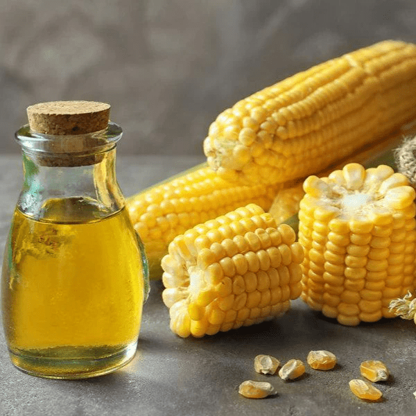
Why combine soybean and corn oil?
- Fatty acid profiles differ. Soybean oil is richer in unsaturated fatty acids (linoleic, linolenic), while corn oil contains more oleic and palmitic. That mix can change the viscosity and spreading behavior on leaves.
- Broader efficacy. Soybean oil has strong data against powdery mildew, mites, and whiteflies (1) (2) (3). Corn oil has been validated in cucumber mildew trials (5). Using both hedges against variability between pests and crops.
- Physical properties. Mixed oils can emulsify more easily and form finer droplets than a single oil, which may improve coverage and reduce visible residues.
Why use both Tween 20 and Tween 80?
- Hydrophilic balance. Tween 20 (polyoxyethylene sorbitan monolaurate) is more hydrophilic, while Tween 80 (polyoxyethylene sorbitan monooleate) is more lipophilic. Together, they stabilize emulsions of mixed triglyceride oils better than either one alone.
- Reduced creaming/separation. A dual-Tween system forms smaller, more stable droplets that resist breaking apart. This means the concentrate stays uniform longer and the spray deposits more evenly on foliage (4).
Step 1. Prepare the concentrate
Mix in a clean container:
- Soybean oil: 200 mL per liter (~760 mL per US gallon)
- Corn oil: 200 mL per liter (~760 mL per US gallon)
- Tween 20: 10 mL per liter (~38 mL per gallon)
- Tween 80: 10 mL per liter (~38 mL per gallon)
- Fill with clean water to reach 1 L (or 1 gal).
Mix for at least 30 minutes, ensure it is uniform. Always mix well before use. This is the concentrate: 20% soybean oil, 20% corn oil, 1% Tween 20, 1% Tween 80.
Step 2. Dilute for spraying
For foliar application:
- Dilution rate: Add ~20mL of concentrate per liter of water (~75 mL per US gallon of water). If pests are present you can increase the rate up to 32mL/L (~120mL/gal).
- Note on coverage: Coverage is critical for this spray to work as it only kills insects on contact or prevents PM by building an oil film on the leaf that prevents spore germination. Without full coverage effectiveness will drop.
This produces a 0.8% oil spray with 0.02% Tween 20 and 0.02% Tween 80 in the final spray solution. Mix well before use.
Shelf life considerations
- Concentrate: A freshly prepared concentrate can stay stable for several weeks if kept sealed, cool, and out of light. Always shake well before use, since some slow separation can occur.
- Diluted spray: Once mixed with water, use the spray the same day. Emulsions can separate within 12-24 hours, and microbial growth in water can destabilize the mix. Discard leftovers rather than storing diluted spray.
- Indicators of instability: Layering, large oil droplets, or visible separation mean the emulsion is breaking, don’t spray that on plants without mixing well again.
Why it works
Soybean oil sprays at 2% suppressed powdery mildew on roses and tomatoes (1), reduced spider mites by 97-99% (2), and deterred whiteflies (3). Corn oil added control of cucumber mildews (5). Tweens stabilize and spread the oils (4).
Bottom line
- Concentrate: 200 mL soybean oil + 200 mL corn oil + 10 mL Tween 20 + 10 mL Tween 80 per liter (or 760 mL + 760 mL + 38 mL + 38 mL per gallon), topped up with water.
- Spray dilution: 75 mL concentrate per gallon of water.
- Final spray: 0.8% oil, 0.02% Tween 20, 0.02% Tween 80.
- Shelf life: Weeks for concentrate (if stored sealed, cool, dark); hours for diluted spray.
This blended, dual-Tween foliar spray is a low-cost, evidence-backed way to add an oil-based control into hydroponic IPM programs.